Just because a fiber link passes data doesn’t mean everything is running smoothly under the hood.
A connector could be dirty, a splice might be dropping more signal than it should or a cable may have been bent too tightly in the ceiling space. The total loss might be acceptable for now, but you could be sitting right on the edge leaving almost no headroom for future maintenance, another splice, or an upgrade to higher speeds.That is precisely why thorough fiber testing needs to answer two key questions, not just one.
- First: How much light signal are you actually losing from end to end?
- Second: Where is that loss happening?
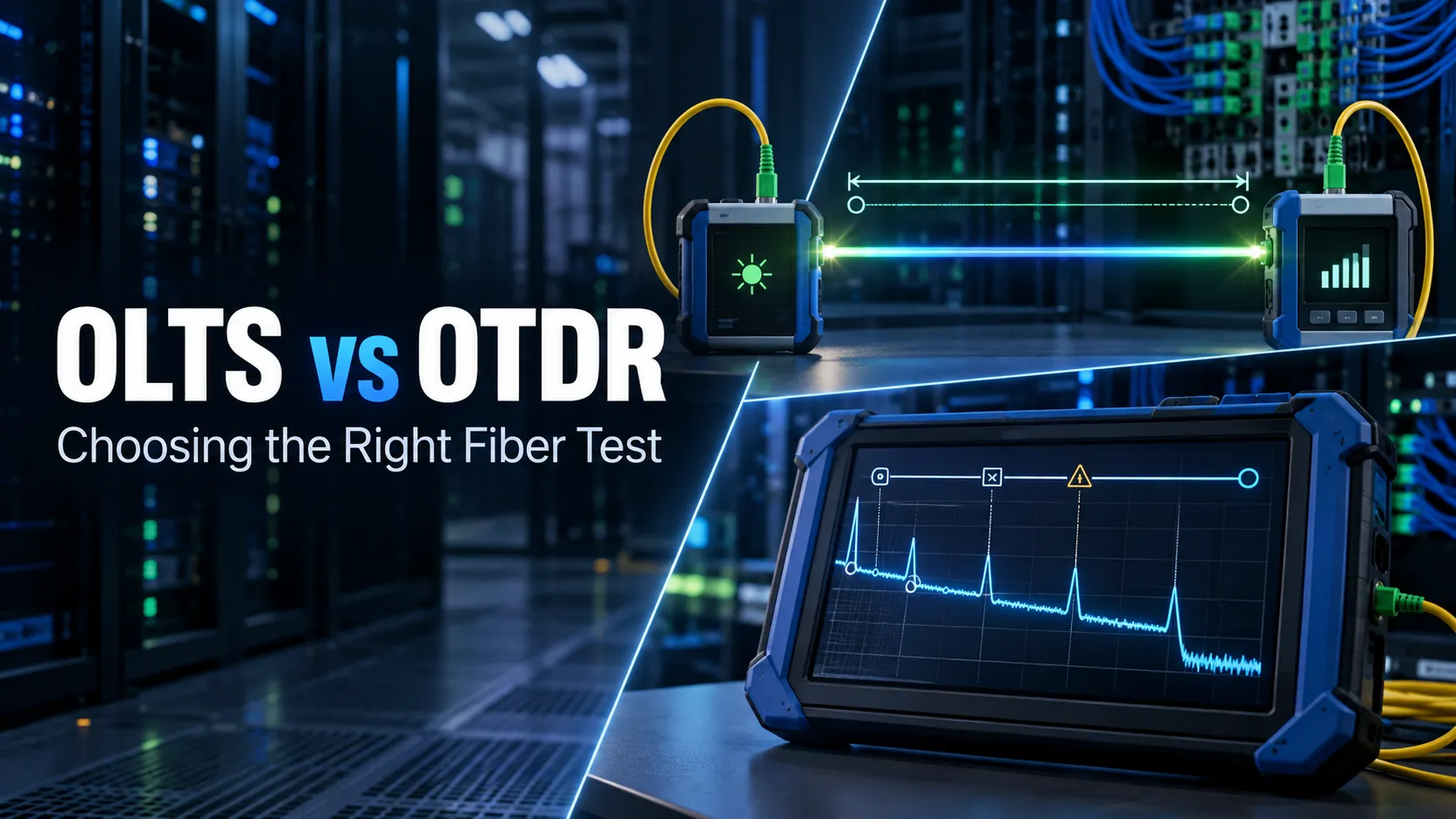
Those questions lead to two different test methods: the Optical Loss Test Set (OLTS) and the Optical Time Domain Reflectometer (OTDR). Understanding OLTS vs OTDR starts with recognizing that each tool answers a different part of the same testing problem.
An OLTS measures end-to-end insertion loss the performance the transmitter and receiver will experience across the complete fiber link. An OTDR looks inside the link, showing the position and behaviour of connectors, splices, bends, breaks and other events. This is the fundamental difference behind OLTS vs OTDR testing.
Neither tool should automatically be considered the “better” one. In practice, the OLTS vs OTDR decision depends on whether you need end-to-end certification, event-level diagnostics, or both.
For a GCC data center, campus backbone or enterprise fiber installation, the right choice depends on what the project needs to prove. In many professional handovers, the strongest answer is not OLTS or OTDR. It is understanding when each measurement is required and when both should be included.
What an OLTS Measures
At its core, an OLTS measures optical insertion loss.
The process is straightforward: a calibrated light source sends a set level of optical power through the fiber and a power meter at the other end measures how much light makes it through. The difference between the two measured in decibels, is your total link loss. Because of this setup, an OLTS tests the fiber under real-world conditions, mirroring how a transmitter and receiver actually communicate from end to end. The result gives you the combined impact of the cable length itself, along with any splices or connections covered by your chosen reference method.
Before testing, you set a reference baseline to establish the starting optical power. As AEM highlights in its TestPro CV100 fiber certification guidance, getting this step right is essential for accurate readings, so make sure your reference cords are clean and in top condition. This makes an OLTS perfect for answering one essential question:
Does this completed fiber link stay within the project’s allowed loss budget?
AEM’s TestPro supports single mode and multimode fiber certification and includes TIA, ISO and configurable loss budget limits. Its fiber results show measured loss, limit and remaining margin at the relevant wavelengths. For installers handing off a new backbone, having a definitive PASS/FAIL result is crucial. However, an OLTS has a key limitation.
If a link shows 2.1 dB of loss when the design expected 1.2 dB, the tester confirms there is a problem, but nothing more. It can’t pinpoint where that extra 0.9 dB loss is occurring. And that’s where the OTDR comes in. This is one of the clearest examples of why OLTS vs OTDR is not a question of choosing one universally superior tester.
What an OTDR Reveals
An OTDR takes a completely different approach to testing fiber.
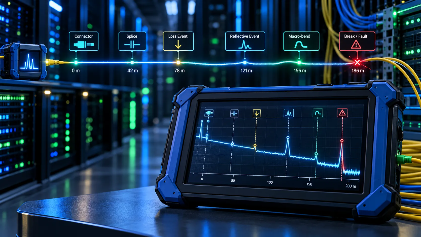
Rather than sending light all the way through the cable and checking what comes out the other end, it fires short pulses of light into the fiber and measures what bounces back through backscatter and reflections. This creates a clear visual trace showing how light behaves at every point along the link’s entire length.
With an OTDR, you can easily map key events across the link, such as:
- Connectors
- Fusion and mechanical splices
- Unexpected loss points
- Reflective events
- Macro-bends or stressed fiber
- Fiber length
- Breaks and their approximate location
As the Fiber Optic Association points out in its OTDR overview, components like connectors and splices show up as distinct events on the trace, while the overall slope reveals signal loss over distance. That visibility makes troubleshooting infinitely easier. In an OLTS vs OTDR workflow, the OTDR provides the location intelligence that a simple end-to-end loss result cannot.
When an OLTS flags that a link has too much loss, an OTDR can pinpoint that almost all of that extra loss is coming from a single connector sitting 186 meters down the line. That gives technicians an exact location to start fixing the problem.
Modern devices make reading these results straightforward by turning raw traces into clear event tables or visual maps. For instance, AEM’s single-mode and multimode OTDR adapters for TestPro and Network Service Assistant locate events, measure loss and reflectance and guide techs straight to high-loss points or faults. Ultimately, an OTDR answers the critical diagnostic question:
What’s happening inside this fiber link and exactly where?
Loss Measurement vs Fault Location
The easiest way to understand OLTS vs OTDR is to imagine a fiber link that fails acceptance testing.
The OLTS reports:
Measured loss: FAIL
This immediately tells the tech that something is off with the signal along the entire path. Next, you hook up the OTDR and it pinpointing the exact spot: High-loss event: Connector at 142 m
Just like that, the team knows precisely where to focus their troubleshooting.That is why viewing an OTDR as just an upgraded replacement for an OLTS is a mistake. They actually test two fundamentally different things.
As the Fiber Optic Association notes, standard cabling guidelines prefer insertion loss testing using a light source and power meter (or OLTS) for certified end-to-end loss, rather than relying solely on OTDR data.
On the flip side, an OLTS won’t help you much when you need to locate a specific fault. If a crew accidentally severs a backbone run between two buildings, simply knowing the line lost all light signal doesn’t get the problem fixed. Knowing that the break sits roughly 417 meters out from Building A changes everything.
It really comes down to a practical distinction:
- OLTS = How much total optical loss does the link have?
- OTDR = Where are the events and losses inside the link?
Both insights are essential whether you’re handling installation, ongoing maintenance, or emergency troubleshooting. That is why OLTS vs OTDR should be treated as complementary testing approaches rather than competing technologies.
When a Project Needs Both Tests
For most high-stakes fiber jobs, running both tests gives you a complete, clear handoff. For teams evaluating OLTS vs OTDR for acceptance testing, this combined approach provides both certification evidence and a diagnostic baseline.
AEM breaks this down into Tier 1 testing for optical loss certification and Tier 2 for adding full OTDR analysis. Their OTDR adapters let you seamlessly pair a trace with TestPro’s single mode or multimode Tier 1 results for a complete Tier 2 workflow. Take a new data center backbone as an example.
The OLTS confirms that Fiber 17 easily clears the project’s loss limits. Meanwhile, the OTDR trace captures the exact physical breakdown of that strand mapping out its length, splices, connections and reflectance. That detail might not feel urgent on day one when everything is working perfectly.
Fast forward two years: routine maintenance happens and that same fiber starts throwing errors. The IT team can instantly run a new OTDR test and overlay the new trace against the original baseline.
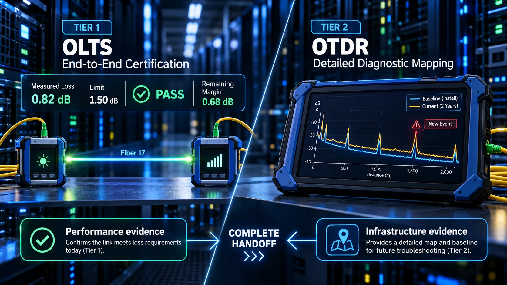
Any newly introduced problem instantly stands out. By combining both tests, you give stakeholders two solid forms of proof:
Performance evidence: proof that the fiber passes total loss requirements.
Infrastructure evidence: a complete map documenting every event along the link.
Not every job requires both levels of testing. Scope should always align with project specifications, network demands, customer expectations and standard guidelines. However, for critical data centers, campus backbones, and high-value enterprise fiber setups, having that detailed diagnostic baseline is well worth it.
Set Reference and Inspection Connectors
Fiber testing demands extreme precision, but your results are only ever as good as the connections you test with.
A dirty reference connector adds unexpected signal loss, easily making a perfectly fine link look like a failure. To make matters worse, plugging a contaminated test cord into a pristine installed connector instantly transfers grime onto the endface. That is why inspecting and cleaning connectors must be done before hooking them up, not just when trying to figure out why a test failed.
As the FOA’s fiber testing guide highlights, the cleanliness and overall state of your reference connectors directly make or break loss measurement accuracy.
Reference cords also need to match the specific fiber type and connector setup you are testing.If they become worn or damaged, the test setup itself becomes part of the problem.
A practical workflow is simple:
- Inspect first.
- Clean if needed.
- Inspect once more.
- Then plug in and run the test.
This same discipline goes for any adapters and couplers linking reference cords to the installed run. Ultimately, a professional handover report should prove the quality of the client’s infrastructure, not document dirt introduced by the test gear itself.
Launch and Receive Fibers
Using launch and receive cables is especially critical when working with an OTDR. Right at the start of a trace, the unit’s powerful light pulse creates a reflection that leaves a temporary blind spot, known as the dead zone.
Without a launch fiber attached, the OTDR won’t be able to evaluate the first connector on your installed run properly. Adding a known length of launch fiber gives the instrument room to settle down before it hits that initial connection. Similarly, attaching a receive fiber at the far end allows the OTDR to measure the final connection accurately.
As the FOA OTDR testing guide explains, launch cables clear the initial dead zone to establish a baseline for the front-end connection, while receive cables ensure the far-end connector gets tested correctly as well.
That means an OTDR trace taken without both cables might look complete on screen, yet completely miss critical details at either end of the link. This setup detail matters in any serious OLTS vs OTDR testing plan because inaccurate OTDR event data can undermine the value of the comparison. Matching the fiber type is just as vital as launch and receive cords must align with the cable under test, complete with matching connectors and high-quality factory terminations.
Wavelengths and Test Direction
Fiber should always be tested at the specific wavelengths called out by its design type and project standards. For instance, AEM’s TestPro platform tests at 850 nm and 1300 nm for multimode fiber and 1310 nm and 1550 nm for single-mode loss certification.
Testing across multiple wavelengths is essential because light behaves differently as wavelengths change. A macro-bend, for example, will often show greater signal loss at higher wavelengths. Comparing readings across wavelengths gives you a much clearer picture of overall fiber health.
Direction of measurement matters just as much. AEM fully supports dual ended and bidirectional testing, with their TestDataPro reporting software logging loss measurements for both Main to-Remote and Remote to Main directions.
Bidirectional OTDR testing can be especially useful around splices because differences in the backscatter characteristics of two fibers can make an event appear to have different loss depending on the direction of measurement. The project specification should define the required wavelengths and direction rather than leaving those choices to the technician after installation.
Compare Results with the Loss Budget
A fiber test result does not mean much without context. Whether your project uses one method or a combined OLTS vs OTDR process, every measurement still needs to be judged against a defined loss budget.
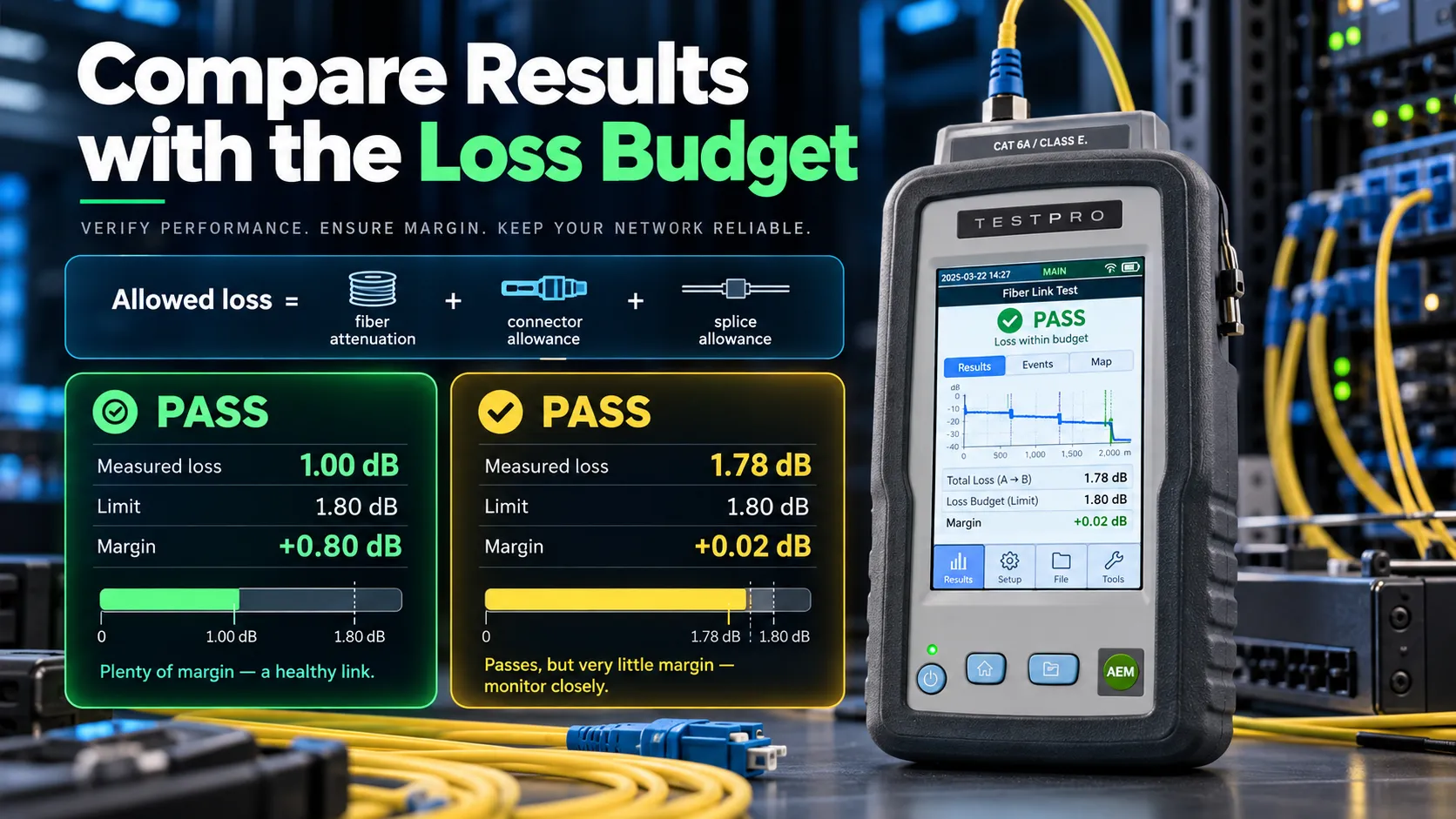
A 1.6 dB result might be excellent for one link and unacceptable for another. That is why every job needs a clear optical loss budget before you start. At a basic level, your budget adds up the loss you expect from the fiber itself, plus all the connectors and splices along the run:
Allowed loss = fiber attenuation + connector allowance + splice allowance
The final project limit should follow the applicable design, cabling standard and application requirements rather than arbitrary generic numbers. AEM’s TestPro can use predefined TIA and ISO limits or customised project loss budgets. Its results then report the actual measured loss alongside the limit and remaining margin. Margin is valuable because passing by 0.80 dB tells a different story from passing by 0.02 dB.
Both register as a PASS on paper, but only one gives you real peace of mind for the long run. If a link comes back dangerously close to the line, it is always worth investigating why instead of just marking it green and moving on.
What to Include in a Fiber Handover Report
A solid fiber handover report should give anyone reading it a complete picture of what went down during testing even if they weren’t on site. When both methods are specified, the report should make the OLTS vs OTDR results easy to distinguish while showing how they support the same acceptance decision.
For every single strand, you’ll want to log the cable or link ID, where it starts and ends, the fiber and connector types, measured length, test setup, wavelengths, direction, the chosen standards or loss limits, measured insertion loss, maximum allowed loss, remaining margin and the final PASS/FAIL result.
If you ran OTDR tests, make sure to attach the trace files along with event details covering connectors, splices, individual event losses, reflectance and exact distances.
Don’t forget to detail the test gear, adapters, reference method and test date as well.
AEM’s TestDataPro software is built to bring all your TestPro data together into clean, structured project documentation instead of leaving files scattered across different field units. That paper trail is worth far more than just getting sign-off on a new install.
It becomes the baseline for future troubleshooting.If a backbone line acts up three years later, the IT team can easily pull up the original baseline trace and compare it to fresh measurements.
Through D3, an AEM Distributor serving contractors, system integrators and enterprise IT teams throughout Dubai, Riyadh and the GCC, teams can access AEM tools for fiber certification, inspection, OLTS testing, OTDR troubleshooting and professional reporting.
D3 focuses on helping you match the right test gear to your specific project needs, not just selling another piece of equipment. That distinction really matters.
When the main question is “Does this fiber meet its overall loss limit?”, grab the OLTS.
When you need to know “Where is the loss or fault located?”, fire up the OTDR.
And whenever a job calls for both performance proof and a detailed baseline map of the cable infrastructure, run both. Because a professional handover shouldn’t just reassure the client with a quick:
“The link works.”
It should leave them with clear evidence of how well it works, what’s happening inside the fiber and exactly where to look if something changes down the line.