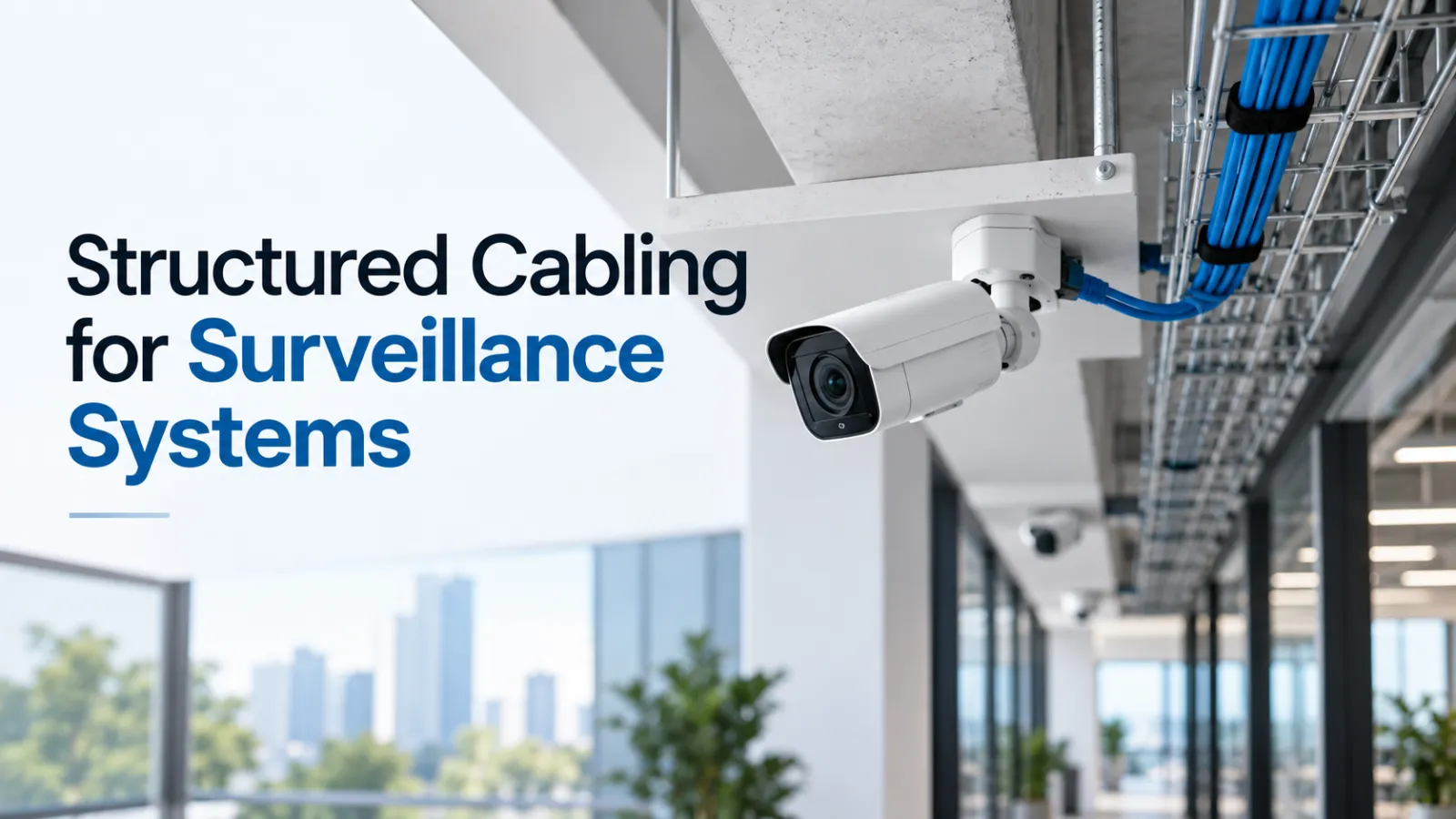
That’s why structured cabling for surveillance isn’t just an accessory; it’s a core component of the security setup itself.
A loose connector, a run that’s too long, cheap copper, damaged wire pairs, or an underpowered PoE switch can lead to dropped connections, slow network speeds, and missing footage. These headaches multiply quickly when you’re managing hundreds of cameras across a warehouse, commercial building, or large campus.
Great surveillance systems don’t start with mounting cameras. They start with building a rock-solid network underneath them.
Why Camera Performance Depends on Cabling Quality
At its core, an IP camera is just another endpoint on your network. What sets it apart is that it runs continuously, pushing video streams 24/7, often from hard-to-reach spots where maintenance is a hassle once installed.
That is why having a solid physical link matters so much.
Take a modern Tiandy IP camera: it can stream high-res video using codecs like S+265, H.265, or H.264, all while drawing power through that same Ethernet line. The cable has to deliver steady data and clean power across the entire distance without failing.
The catch is that a cable can look fine on the outside while causing non-stop issues internally. Maybe the wire pairs were untwisted too much during termination, or a plug was badly crimped. Perhaps someone pinched the cable against a ceiling grid, pulled it too tight around a corner, or exceeded the bend radius.
None of those defects will show up just by glancing at the RJ45 connector. Real-world security environments only complicate things further.
Cabling often runs through sweltering ceiling plenums, open warehouses, outdoor housings, or right next to high-voltage equipment. Tight cable bundles carrying high PoE wattage build up heat, and harsh surroundings degrade both data integrity and long-term durability over time.
So picking the right category rating is only part of the solution. Even Cat 6 or Cat 6A cable will underperform if the installation is sloppy. Every piece of the channel—the cabling, jack modules, patch panels, patch cords, and terminations—needs to perform seamlessly together.
Camera topology also deserves attention. Unlike a desktop computer, many IP cameras are mounted directly to a ceiling, wall, or pole. Installers may therefore terminate the horizontal cable directly into a field-terminable plug rather than installing a conventional wall outlet.
This setup is known as a Modular Plug Terminated Link (MPTL). Security cameras are a primary driver behind the rise of field-installable plugs and MPTL deployments.
It is a convenient, clean design for cameras, but only if the terminations and testing are handled properly. After all, even the best camera cannot overcome a faulty wiring foundation beneath it.
PoE, Distance, Bandwidth, and Switch Planning
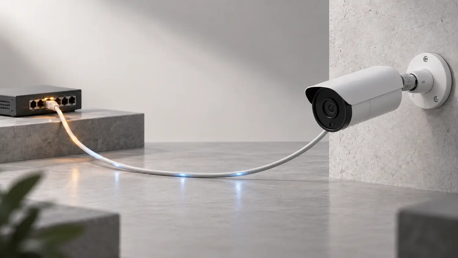
Thanks to Power over Ethernet, setting up security cameras has gotten a whole lot easier.
Instead of running a dedicated power outlet to every single camera location, a single network cable handles both video data and electrical power straight from your switch or injector.
The Ethernet Alliance describes PoE as a standardized way to deliver power right alongside Ethernet data, highlighting IP cameras as one of its core, proven uses.
That said, planning for PoE takes more than just checking if your switch has PoE-capable ports.
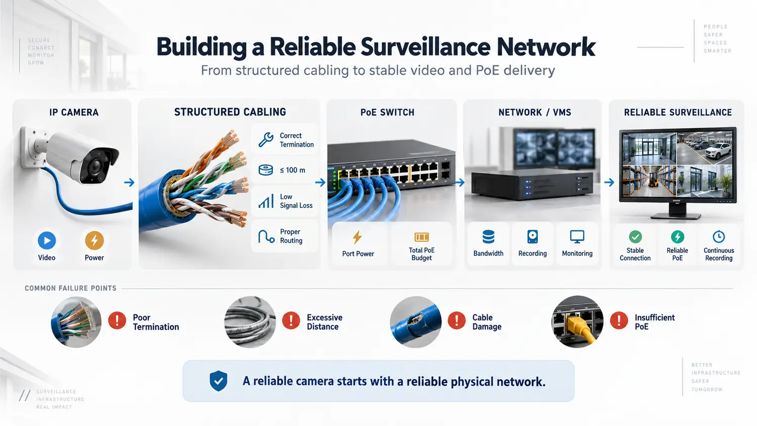
You really need to look closely at power output per port alongside the switch’s overall power budget.
Say you have a 48-port switch running 40 cameras. Each camera might test fine on its own, but the switch still needs sufficient total wattage capacity to power every device running at the same time.
This becomes particularly important with PTZ cameras, IR illumination, heaters, and more advanced surveillance devices because their peak power requirement may be much higher than that of a basic fixed camera.
Distance brings another challenge to keep in mind. Standard Ethernet and PoE copper cabling are built around a maximum 100-meter channel limit. IEEE PoE standards assume the power source and the powered device are separated by no more than 100 meters of total cabling and connection points.
When runs go beyond that, you need proper engineering rather than just tacking on another 30 meters of wire and hoping for the best.
As distance increases, insertion loss affects the data signal, and electrical resistance increases voltage loss for PoE. Specialized extended-reach cabling, additional network infrastructure, fiber, or appropriately designed extenders may therefore be required depending on the project.
Bandwidth also needs to be calculated at switch level.
One camera may generate only a few megabits per second, but 100 cameras recording simultaneously create a very different traffic profile.
The project should account for:
- Camera resolution and configured bitrate
- Frame rate
- Compression method
- Continuous versus event recording
- Main and secondary streams
- Analytics traffic
- Number of simultaneous playback users
- Traffic moving toward the NVR or VMS
- Expected future camera expansion
Just because a switch has enough open ports doesn’t mean it has the necessary uplink bandwidth or PoE capacity to handle the load.
That is why it’s so critical to involve your network team right from the design phase, well before cameras start dropping offline in production.
Cable Testing and Certification Requirements
Plugging in a laptop to check if the network connects isn’t the same as actually certifying a cable.
Sure, a basic continuity tester can tell you if the wires are connected end-to-end. But it can’t prove that the installed run actually meets the performance standards required for its cabling category.
For any business investing in structured infrastructure, that distinction is crucial. True certification checks key parameters like wiremap, length, insertion loss, return loss, and crosstalk against strict industry limits. The goal is to ensure the link performs exactly as expected for its specified category.
Today’s ANSI/TIA-568.2-E standard sets the guidelines for balanced twisted-pair cabling and components, with TIA’s TR-42.7 committee defining performance limits, qualification procedures, and testing methods.
Surveillance setups using MPTL layouts need extra attention here.
AEM’s MPTL testing guidelines point out that you need to test an MPTL run using a permanent-link adapter on one end and a category-matched patch-cord adapter on the plug end, measured against proper MPTL limits.
That’s an essential detail to get right.
Relying on a standard channel adapter just because it physically plugs in won’t give you a valid, standards-compliant MPTL certification.
Tools like the AEM TestPro CV100 handle both copper certification and network validation, letting installers and IT staff move past simple continuity checks and generate real, documented test results for every link.
For security projects, you’ll also want to test PoE performance under actual operational loads.
A cable can successfully negotiate PoE and still struggle when a powered device begins drawing its required load. AEM’s Network Service Assistant includes PoE load and validation testing alongside wiremap, distance-to-fault, Cat 5e/6/6A qualification, and Multi-Gig testing.
Testing should answer more than:
“Is the cable plugged in?”
It should clearly prove:
“Can this installed link reliably support the data rate and power requirement we designed it for?”
That is a much more useful handover result.
Common Installation Problems
Most security network failures start with small installation shortcuts that seem harmless at the time.
Excessive cable length is a classic example. An installer hooks up a far-off gate or parking camera using a copper run that stretches way past the standard channel distance, simply because setting up fiber or an extra telecom room feels like too much hassle.
It may work initially, then become unstable under PoE load or environmental changes.
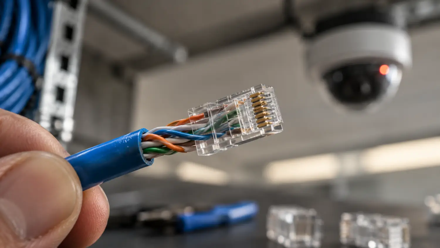
Poor termination causes endless headaches, too. Untwisting wire pairs too much, improperly seating conductors, or using cheap field plugs will wreck your return loss and crosstalk, even if a basic continuity test says the pinout is correct.
Incorrect bend radius and physical damage happen when installers yank cables around tight corners or cinch zip ties way too tight on bundles.
Running data cables alongside high-voltage wiring floods the line with electromagnetic interference. Proper routing pathways and separation distance need to be baked into the initial layout, not figured out on the fly during installation.
PoE brings its own set of real-world quirks into the mix.
Thick cable bundles carrying higher PoE currents naturally generate heat. Conductor gauge, bundle size, ambient temperatures, and cable heat ratings all need to be considered when designing powered cabling systems.
Here are a few other common slip-ups on job sites:
- Running indoor-rated cable outside
- Leaving outdoor connections unprotected from moisture
- Stringing unshielded outdoor copper runs between separate buildings
- Combining cheap patch cords with high-grade certified infrastructure cable
- Forgetting to clearly label switch ports
- Assigning the wrong PoE class to a connected camera
- Overlooking surge protection and grounding needs
- Plugging every single camera into one switch without a single backup point
- Leaving zero headroom in power or network capacity for future additions
A system might squeak by during handover despite a few of these flaws.
The real test comes months down the line when seasons change, ten new cameras get added, or a technician has to troubleshoot an unstable camera in the middle of the night.
Documentation for Maintenance and Expansion
Maintaining structured cabling is so much simpler when every single run has its own clear identifier.
A label like “Warehouse Camera 37” ought to give your network team immediate context.
In an ideal setup, they can instantly trace which patch panel port it links to, which switch and port feed it network access, the exact physical route the cable takes, and the original certification specs recorded at setup.
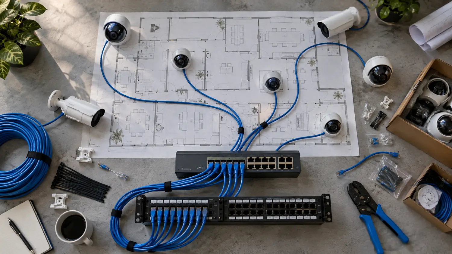
At a baseline, solid surveillance documentation should capture:
- Camera ID and physical location
- Cable identifier
- Telecommunications room
- Patch-panel and port number
- Switch name and switch port
- Cable category
- Approximate route and link length
- PoE requirement
- VLAN or network assignment
- Certification result
- Installation date
Detailed, professional test reporting makes all this documentation far more actionable.
By integrating with TestDataPro, the AEM TestPro platform organizes and shares cable-certification data seamlessly, turning test results into accessible project documentation rather than keeping them stuck inside the tester device. This extra step really pays off whenever it is time to expand.
For instance, if you need to deploy 40 more Tiandy cameras across a logistics facility, your team can easily verify open switch ports, existing cable pathways, PoE headroom, and past certification files long before hardware lands on site.
Good documentation also saves massive amounts of time during troubleshooting.
Whenever a camera drops connection, technicians do not have to waste hours tracing mystery lines through a cluttered server rack—they know exactly where the run terminates and can jump straight to testing.
The core strategy behind D3 is treating physical surveillance networks as a key part of your broader enterprise IT architecture. Offering both the Tiandy surveillance portfolio and AEM network testing solutions, D3 equips GCC projects with reliable cameras as well as the certification gear needed to validate the wiring beneath them.
That holistic view matters because reliable security monitoring depends on far more than just the camera itself.
Surveillance Cabling Checklist
Before signing off on an IP surveillance cabling job, run through this quick sanity check to make sure everything is built to last:
- Has every camera location been surveyed?
Confirm distance, environment, pathway, and mounting requirements before pulling cable. - Are you using the right cable for the job?
Pay attention to category ratings, wire construction, indoor/outdoor ratings, and local conditions. - Are copper channels within their designed distance?
Do not treat the conventional 100-meter Ethernet channel as an optional recommendation. - Have long-distance cameras been properly planned?
Use fiber, additional network closets, or dedicated extenders instead of stretching copper past its limits. - Is the PoE standard correct for every camera?
Check the individual device requirement rather than assuming every PoE camera consumes the same power. - Does the switch have enough total PoE power budget?
Add up the total power needs of all connected devices at full load and leave room for expansion. - Is there enough switch bandwidth to handle the traffic?
Account for bitrates, frame rates, video streams, and uplinks—don’t just count open ports. - Have terminations been installed correctly?
Inspect plugs, jacks, pair twist, and workmanship before devices are mounted permanently. - Are MPTL connections being tested correctly?
Use proper patch-cord adapters and MPTL test profiles instead of standard channel adapters. - Has every permanent link been fully tested or certified?
Make sure the testing depth matches project specs and category standards. - Has PoE performance been validated?
Where power delivery is critical, confirm behavior under the expected load. - Are cable bundles and pathways set up safely for PoE heat?
Consider wire gauge, bundle sizes, ambient temperatures, and heat dissipation. - Are outdoor connections protected?
Account for water ingress, surge exposure, enclosures, and environmental conditions. - Is every cable labeled cleanly at both ends?
Maintain a consistent labeling standard across cameras, patch panels, and switch ports. - Are complete test reports included in handover docs?
Provide documented proof of cable certification, not just a verbal confirmation that video popped up. - Is there room built in for future growth?
Leave extra space in cable pathways, patch panels, switches, PoE headroom, and uplinks for expansion.
Even the highest-end cameras will run into trouble if the network foundation beneath them is weak.
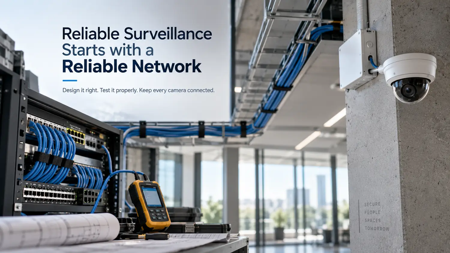
That’s why structured cabling for surveillance needs to be designed, tested, and documented like critical IT infrastructure—not an afterthought.
For GCC businesses, integrators, and enterprise teams, D3 pairs high-performance Tiandy IP surveillance with advanced AEM testing gear to guarantee your underlying network is ready from day one.
Because when a critical security event happens, the last thing you want to discover is that the camera was ready to record—but the cable failed to keep it online.